Aftermarket activity

Industrialization of innovative projects

Back to the list

Oxygen sensors

The advent of the autonomous car has highlighted the fundamental importance of having good sensors. That being said, we have long been committed to providing effective – and reliable – sensors to our customers. So whether you are looking for engine and transmission sensors, or for comfort and safety – not to mention emissions and e-mobility – you should definitely take a look at our range.

Back to the list
Oxygen
sensors

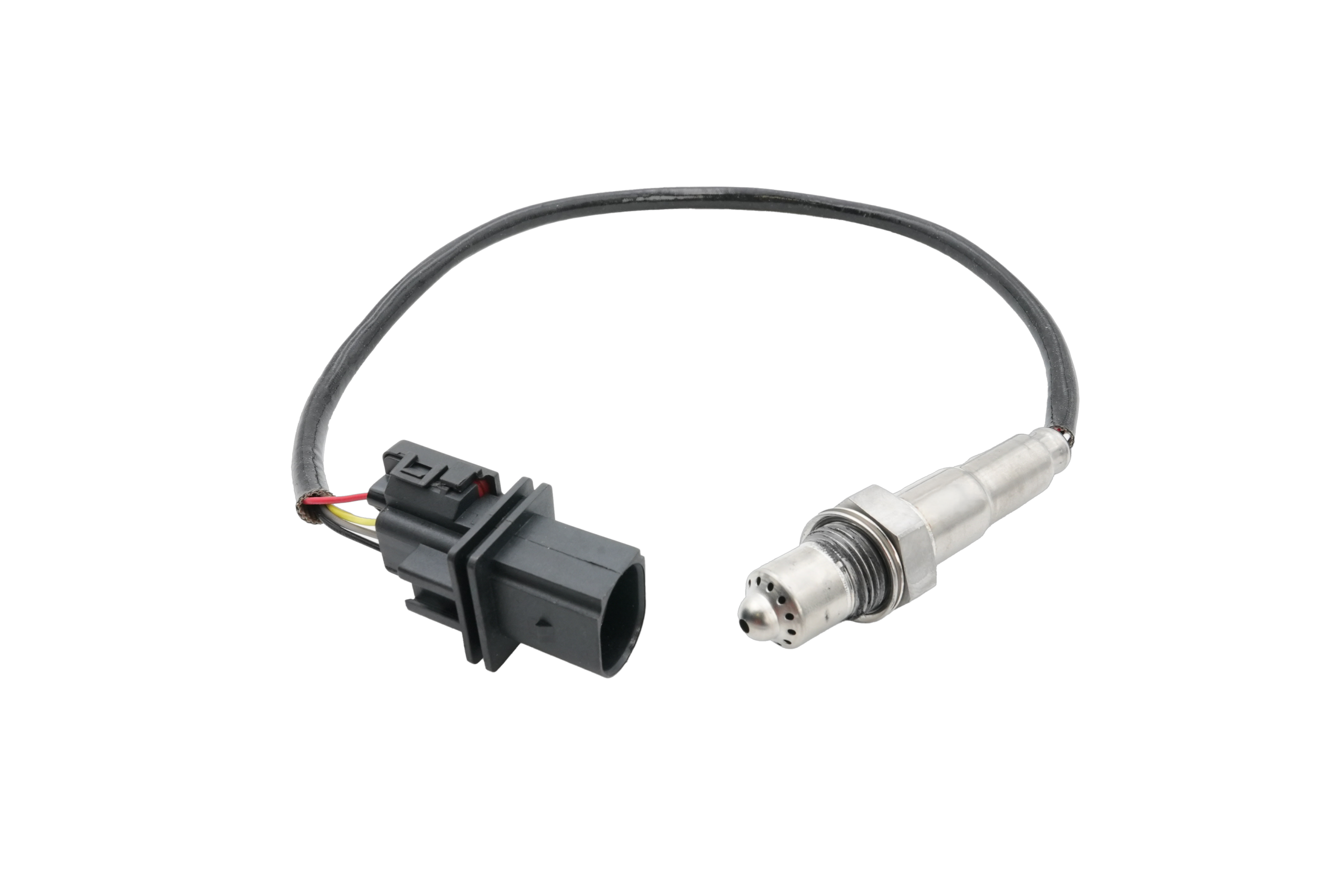
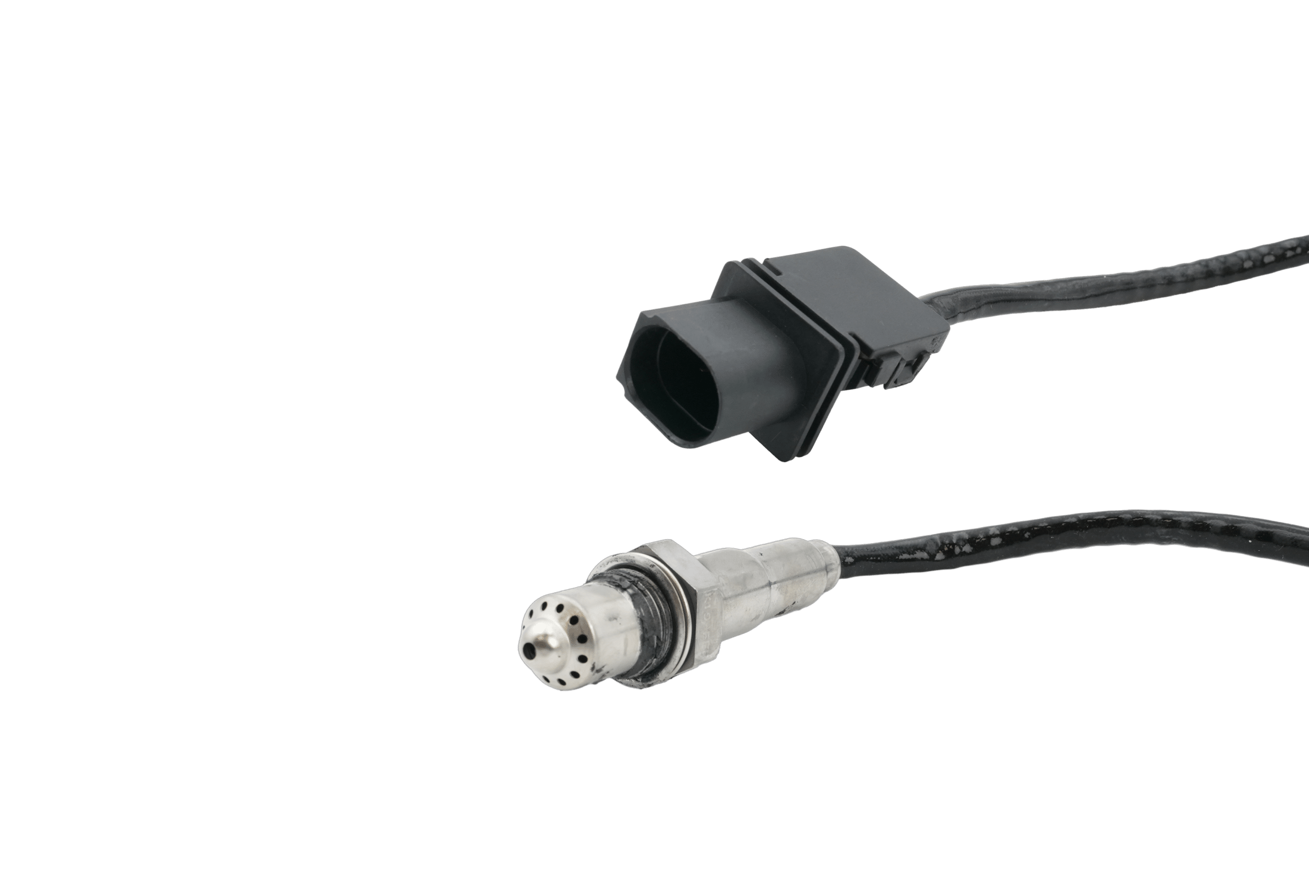
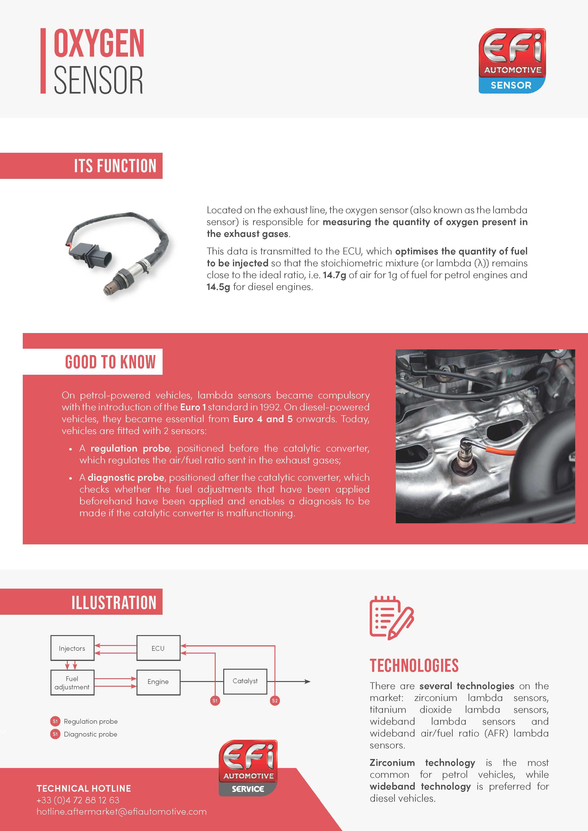
Located in the exhaust system, the oxygen sensor checks the level of pollutant emissions (hydrocarbons, carbon monoxide, and nitrogen oxide) by measuring the oxygen content of the exhaust gases produced by the combustion of the air-fuel mixture. This information is transmitted to the ECU, which then optimizes the quantity of fuel to be injected, so that the stoichiometric (or lambda [λ]) mixture remains close to the ideal ratio, which is 14.7 g of air to 1 g of fuel for petrol engines and 14.5 g for diesel engines.

Also called lambda sensor, the oxygen sensor has been mandatory since the Euro 3 standard was introduced in 2001. This requires vehicles to be fitted with two sensors, whether it is for diesel or petrol engines. As a result, the exhaust system has a regulation sensor and a diagnostic sensor, located respectively before and after the catalytic converter. The regulation sensor informs the ECU about the oxygen content, whereas the diagnostic sensor ensures that the catalytic converter is operating correctly (by checking the corrective actions applied by the measurement of the first sensor).

Technologies
Technical information
Frequently asked questions
Resources
Technologies

ZIRCONIA LAMBDA SENSORS

This is the most used technology on the market and works by comparing two atmospheres: exhaust gases and air. The difference in oxygen content between the two gases generates a voltage in the sensor. The sensor then indicates to the electronic control module (ECM) the need to adjust the mixture accordingly. If the mixture is too rich, the voltage will be high, and conversely, if it is too lean, the voltage will be low.

Zirconia oxygen sensors require a minimum exhaust temperature of 300°C for the sensor to be active. For most types of sensor technology, as is the case with this one, the internal heating element is made of ceramic material to reduce the sensor latency time.

TITANIUM DIOXIDE LAMBDA SENSORS

Unlike the one described above, this technology does not generate any electrical voltage to adjust the mixture. In this case, the sensor works by way of a ceramic element that is sensitive to titanium dioxide. The sensor is therefore placed in contact with the exhaust gases, without needing any information on the external air.

This type of sensor is continuously heated, as it is when the temperature is relatively high (minimum of 500°C) that the sensor is sensitive to variations in the oxygen content of the exhaust gases. This difference generates a variation in the electrical resistance of the sensor element. If the mixture is too rich, the resistance drops to minimum values, and if the mixture is too lean, it reaches maximum values.

Note: titanium dioxide and zirconia oxygen sensors are not interchangeable, as they differ both in terms of their dimensions and their operating strategy for assessing the signal from the sensor (voltage vs. non-voltage).

BROADBAND LAMBDA SENSORS

Unlike the zirconia and titanium dioxide oxygen sensors, which send a binary response to the ECM, broadband technology sends continuous information to the ECM, corresponding to the lambda value detected. It consists of two electrochemical cells which operate simultaneously. One of these cells (the measuring cell) measures whether the mixture is rich or lean, while the second (the pumping cell) reacts, conditioned by the first and the quantity of oxygen in the exhaust gases. The joint operation of the cells results in an electrical current which is positive for a lean mixture, negative for a rich mixture, and zero in the case of a perfect lambda. The current generated by these sensors is calibrated and must be converted into voltage so that the vehicle’s ECU can process the information.

This is why broadband technology is more accurate than the previous two, as it measures the exact composition of exhaust gases, making it suitable for both diesel and petrol vehicles.

However, there are three generations of broadband sensors on the market. The first contains an external air reference channel like that in zirconia oxygen sensors. The second generation no longer needs this channel to operate. The absence of a channel means lower power consumption, shorter warm-up times, and greater signal stability. The third generation relates to the air-fuel ratio broadband sensor. Because this is specific, it will be described in the next section.

Note: depending on the vehicle applications, first- and second-generation broadband oxygen sensors may be required (and are still available on the market) but are in no way interchangeable.
AIR-FUEL RATIO BROADBAND OXYGEN SENSORS

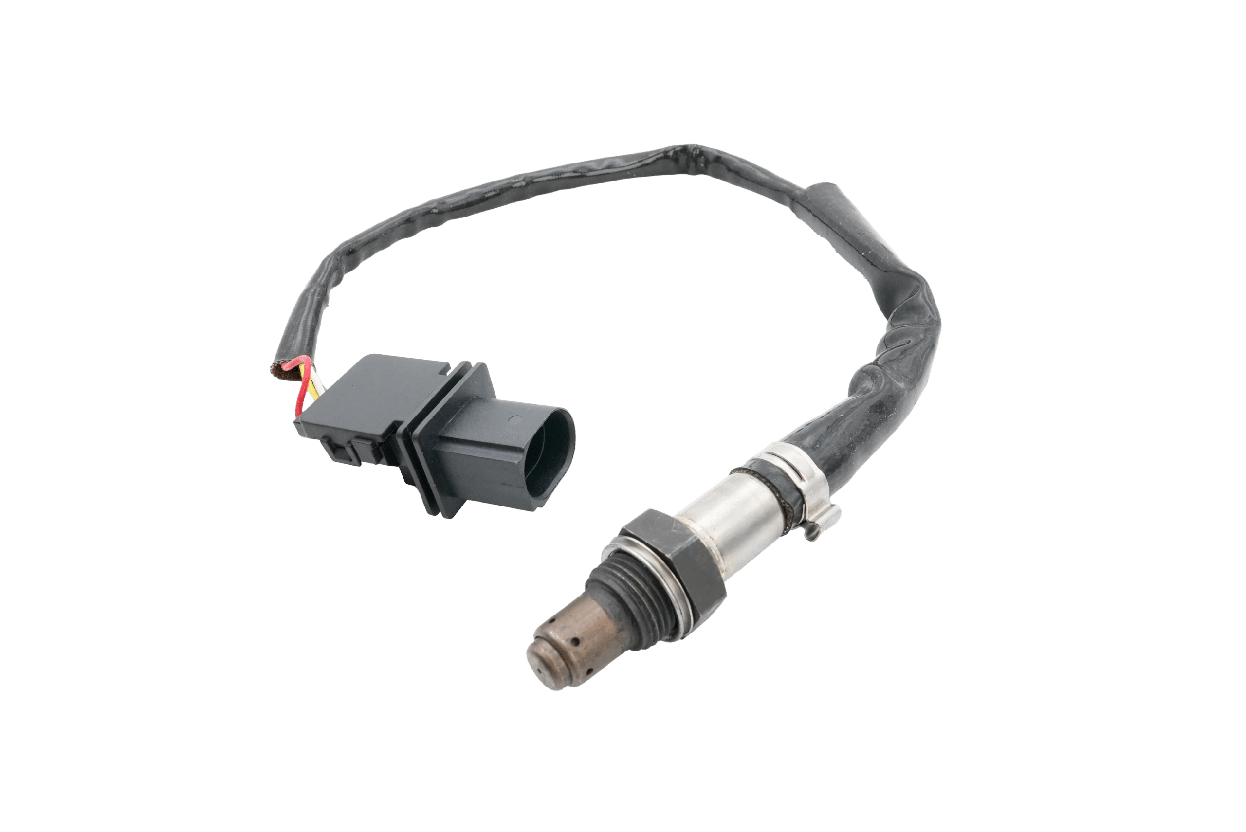
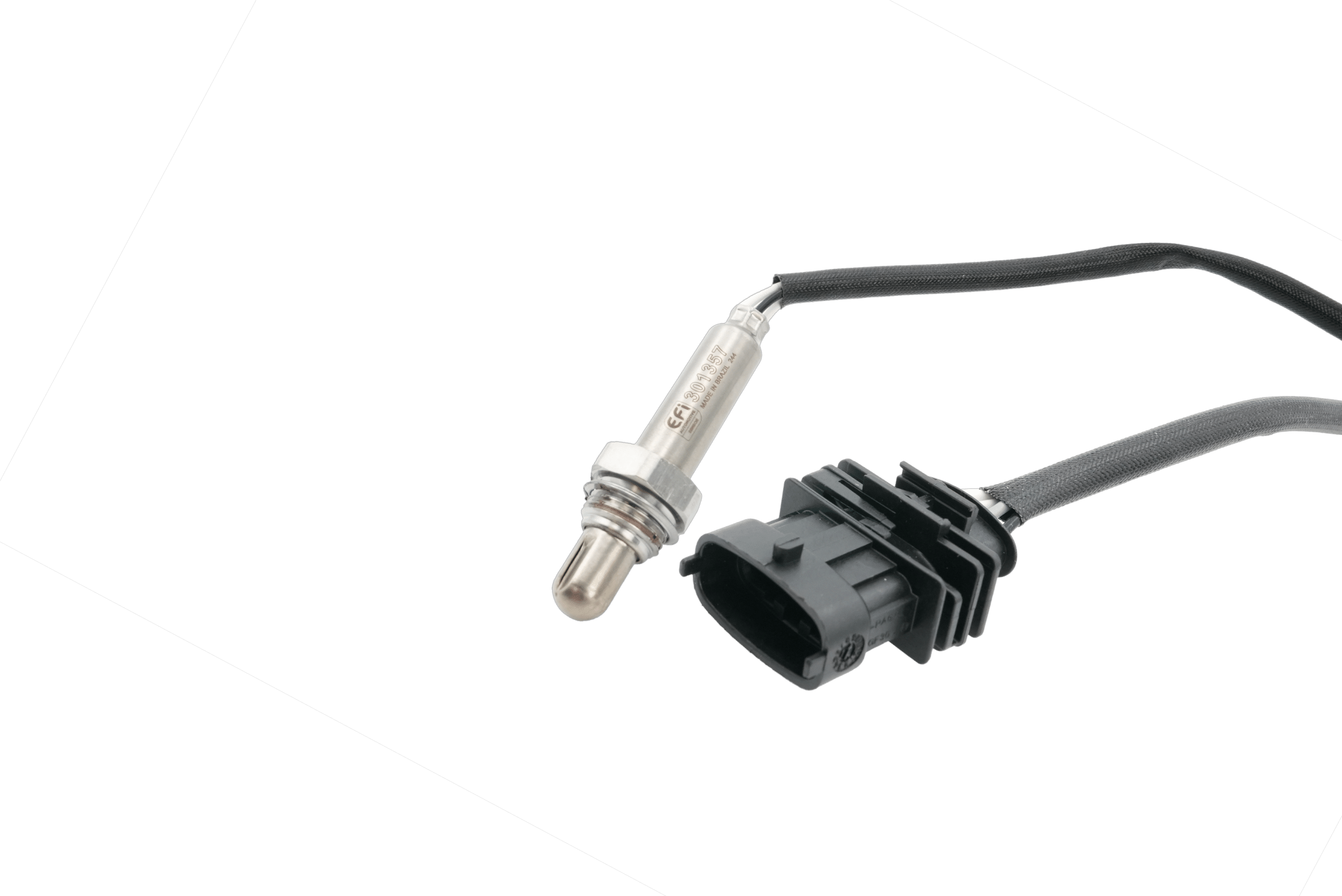
This section draws on previous technology, but with its own specificity. The operation is the same, but this type of sensor has only one electrochemical cell, which means less platinum is used. This special feature means one less wire on the sensor, which therefore has four, unlike standard broadband lambda sensors, which have five.

In general, these sensors are more sensitive and efficient than conventional lambda sensors, due to the way in which they measure the air-fuel ratio and the various output signals that they produce to indicate the result. More concretely, a conventional sensor transmits a low voltage (between 0 V and 0.8 V), converting this low voltage into a high one at around lambda 1. An air-fuel ratio sensor transmits a low direct current (between -10 mA and +10 mA).

This value enables the ECU to make precise adjustments, significantly reducing any excess or insufficient fuel supply. This enables a reduction in fuel consumption and improves driving comfort.

Technical information

SYMPTOMS

The following symptoms are frequently associated with the failure of an oxygen sensor:

  • Fault indication on the dashboard (engine indicator light);
  • Increased exhaust gas emissions (CO, NOx, and HC);
  • Power loss and irregular engine idling;
  • Non-linear accelerations;
  • Increased fuel consumption (+15%).

DIAGNOSIS PROCEDURE

It is important to visually inspect the oxygen sensor to determine whether it is faulty. It is therefore strongly recommended that the following components are checked:

  • The sensor’s wiring (presence of burnt, damaged, corroded and/or deteriorated wires);
  • The connector of the sensor’s harness (presence of twisted pins, loose connections, and/or traces of corrosion);
  • The metallic casing of the oxygen sensor, to make sure that it is not clogged up (mixture too rich) and that it is free from any shiny, gray, or white deposits – if such deposits are present, this means that other elements (such as lead or oil) are the issue and are polluting the sensor.

It is also possible to use a multimeter to check that the sensor is working properly, by ensuring that the passing voltage is indeed present at the output of the connector. Depending on the technology, the values to be checked are as follows:

  • Zirconia lambda sensor:
    • Upstream sensor: 0,1 < 0,9 V
    • Downstream sensor: 0,6 < 0,7 V
  • Titanium dioxide oxygen sensor:
    • Upstream sensor: 0 < 5 V
    • Downstream sensor: 0,6 < 0,7 V
  • Broadband oxygen sensor:
    • Upstream sensor: 0+2 mA (mixture too rich/0-2 mA (mixture too lean)
    • Downstream sensor: 0,6 < 0,7 V

If the preceding tests are inconclusive, your vehicle’s oxygen sensor needs to be replaced.

CAUSES OF FAILURE

An oxygen sensor may no longer be working due to:

  • Contamination resulting from unburnt substances linked to misfiring and/or the oil;
  • Incorrect fitting of the sensor, leading to the intake of parasitic air;
  • Damage caused by exhaust leaks;
  • Damage linked to silica from gas emissions, an excessively rich air-fuel mixture, high oil consumption, contamination of antifreeze;
  • Exhaust gas overheating;
  • Wear over time (replacement is generally required at between 50,000 and 160,000 km, depending on the technology).

INSTALLATION INSTRUCTIONS

To ensure fast and efficient installation of a specific oxygen sensor, please refer to the following instructions:

  1. Make sure that the engine is cold before removing the oxygen sensor.
  2. First, disconnect the battery’s negative terminal.
  3. Disconnect the connector from the sensor to be replaced. If you meet resistance during removal, spray the oxygen sensor with a releasing agent and leave it to act for 10 minutes.
  4. After removing the old sensor, position the new one in place, ensuring that the cable is not twisted, kinked, and/or trapped.
  5. Secure the oxygen sensor, adhering to the recommended tightening torque using a torque wrench (depending on the manufacturer: 40 Nm to 60 Nm in most cases).
  6. Connect and position the cable as it was originally laid, ensuring that it is not too close to the exhaust manifold or any other hot engine component.
  7. Clear the error memory if necessary.

There are also universal lambda sensors on the market which come without a connector, allowing you to reuse the one already present on the vehicle. Universal sensors are less expensive but increase the risk of fitting errors.

To ensure fast and efficient installation of a universal oxygen sensor, please refer to the following instructions:

  1. Make sure that the engine is cold before removing the oxygen sensor.
  2. First, disconnect the battery’s negative terminal.
  3. Disconnect the connector from the sensor to be replaced. If you meet resistance during removal, spray the oxygen sensor with a releasing agent and leave it to act for 10 minutes.
  4. After removing the sensor, cut its cables, separating the connector from the rest of the part and ensuring that you leave enough cable for the splice later on.
  5. Remove the insulation in accordance with the length indicated, taking care not to damage the cable’s metal core.
  6. Insert the stripped cables from the connector into the sockets on the new sensor, taking care to precisely match the colors of the cables.
  7. Flatten the sockets, then apply heat to the heat-shrink tubing to hermetically secure the junction between the connector and the new sensor.
  8. After removing the old sensor, position the new one in place, ensuring that the cable is not twisted, kinked, and/or trapped.
  9. Secure the oxygen sensor, adhering to the recommended tightening torque using a torque wrench (depending on the manufacturer: 40 Nm to 60 Nm in most cases).
  10. Connect and position the cable as it was originally laid, ensuring that it is not too close to the exhaust manifold or any other hot engine component.
  11. Clear the error memory if necessary.

INSTALLATION TIPS

As the oxygen sensor is essential to the correct operation of the engine, it is important to follow certain advice when replacing this part:

  • When replacing the catalytic converter, the diagnostic sensor must be replaced to avoid damage.
  • Comply with the tightening torque recommended by the manufacturers: 40 Nm to 60 Nm (depending on the different types of technology).
  • Replace both of your vehicle’s oxygen sensors at the same time. Having one new sensor and one used sensor can lead to incorrect measurements which could affect the adjustments of the electronic control module (ECM).

PREVENTIVE INFORMATION

The above items are provided for information purposes only. They do not replace the advice of a qualified technician or mechanic. We strongly recommend that you consult a professional if you are unsure of what to do. Otherwise, we cannot accept responsibility for any damage to your vehicle.

Frequently asked questions
What symptoms should I look out for?

If you notice an orange engine indicator light on your dashboard, then the oxygen sensor is in a critical condition. The appearance of this indicator light will, in most cases, be associated with an increase in exhaust gas emissions (CO, NOx, and HC), and in fuel consumption (+15%). It is likely that the vehicle will lose power and accelerate in a non-linear manner, only allowing you to drive home or to the nearest garage at low speed. The appearance of irregular engine idling is another sign which may point to the failure of the oxygen sensor.

How to identify the fault?

Firstly, we strongly recommend that you visually check the oxygen sensor, and more specifically its wiring (presence of burnt, damaged, corroded and/or deteriorated wires), as well as the connector of the sensor’s harness (presence of twisted pins, loose connections, and/or traces of corrosion).

We also recommend that you check the metallic casing of the oxygen sensor, to make sure that it is not clogged up (due to an excessively rich mixture) and that it is free from any shiny, gray and/or white deposits caused by contamination from external elements such as lead or oil.

Secondly, you can use a multimeter to test whether your sensor is working properly, by checking that voltage is indeed present at the output of the connector. Depending on the technology, the values to be checked are as follows:

  • Zirconia lambda sensor:
    • Upstream sensor: 0,1 < 0,9 V
    • Downstream sensor: 0,6 < 0,7 V
  • Titanium dioxide lambda sensor:
    • Upstream sensor: 0 < 5 V
    • Downstream sensor: 0,6 < 0,7 V
  • Broadband lambda sensor:
    • Upstream sensor: 0+2 mA (mixture too rich) / 0-2 mA (mixture too lean)
    • Downstream sensor: 0,6 < 0,7 V

If the preceding tests are inconclusive, then it would appear that you will need to replace your vehicle’s oxygen sensor(s).

Why does my oyxgen sensor need replacing?

There are many possible reasons for lambda sensor failure. These include contamination resulting from unburnt substances linked to misfiring and/or the oil. Its replacement may be linked to incorrect fitting, leading to the intake of parasitic air, or to exhaust gas overheating.

Deterioration may have been caused by exhaust leaks, or damage may be present linked to silica from gas emissions, an excessively rich air-fuel mixture, or contamination of antifreeze.

Although lambda sensors meet very strict standards, they do not last forever, and their environment is particularly demanding. The lambda sensor may simply need replacing because of wear over time (replacement is generally required at between 50,000 and 160,000 km, depending on the technology).

What are the installation instructions?

We recommend that you follow the steps below to replace your specific oxygen sensor as efficiently as possible and to minimize the risk of any error:

  1. Make sure that the engine is cold before removing the oxygen sensor.
  2. First, disconnect the battery’s negative terminal.
  3. Disconnect the connector from the sensor to be replaced. If you meet resistance during removal, spray the oxygen sensor with a releasing agent and leave it to act for 10 minutes.
  4. After removing the old sensor, position the new one in place, ensuring that the cable is not twisted, kinked, and/or trapped.
  5. Tighten the oxygen sensor, complying with the recommended tightening torque using a torque wrench (depending on the manufacturer: 40 Nm to 60 Nm in most cases).
  6. Connect and position the cable as it was originally laid, ensuring that it is not too close to the exhaust manifold or any other hot engine component.
  7. Clear the error memory if necessary.

If you have purchased a universal oxygen sensor that requires the reuse of the old connector, we advise you to follow the steps below again:

  1. Make sure that the engine is cold before removing the oxygen sensor.
  2. First, disconnect the battery’s negative terminal.
  3. Disconnect the connector from the sensor to be replaced. If you meet resistance during removal, spray the oxygen sensor with a releasing agent and leave it to act for 10 minutes.
  4. After removing the sensor, cut its cables, separating the connector from the rest of the part and ensuring that you leave enough cable for the splice later on.
  5. Remove the insulation in accordance with the length indicated, taking care not to damage the cable’s metal core.
  6. Insert the stripped cables from the connector into the sockets on the new sensor, taking care to precisely match the colors of the cables.
  7. Flatten the sockets, then apply heat to the heat-shrink tubing to hermetically secure the junction between the connector and the new sensor.
  8. After removing the old sensor, position the new one in place, ensuring that the cable is not twisted, kinked, and/or trapped.
  9. Secure the lambda sensor, adhering to the recommended tightening torque using a torque wrench (depending on the manufacturer: 40 Nm to 60 Nm in most cases).
  10. Connect and position the cable as it was originally laid, ensuring that it is not too close to the exhaust manifold or any other hot engine component.
  11. Clear the error memory if necessary.
hat tips should I use to extend the life of my oxygen sensor?

To prolong the service life of your lambda sensors, we strongly recommend that you follow the fitting recommendations below:

  • When replacing the catalytic converter, the diagnostic sensor must be replaced to avoid damage;
  • Comply with the tightening torque recommended by the manufacturers: 40 Nm to 60 Nm (depending on the different types of technology);
  • Replace both of your vehicle’s lambda sensors at the same time. Having one new sensor and one used sensor can lead to obsolete measurements which could adversely affect the adjustments of the electronic control module (ECM).
Resources
This tab contains all the documents available relating to oxygen sensors.
Summary sheet
Find out more about oxygen sensors.
Download